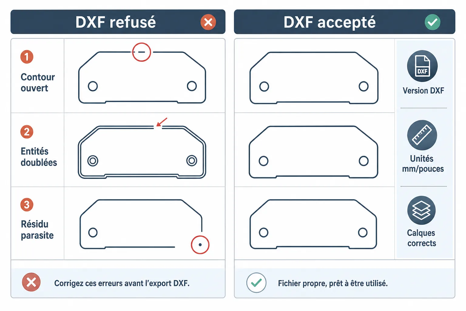
In short: a DXF drawing can stop a laser or plasma cut for reasons that are usually avoidable. Open contours, duplicate entities, wrong layers: it is the same handful of problems every time. Spotting them early avoids expensive round trips.
What cutting software actually expects from a DXF
A DXF file is not just a drawing. It is a list of instructions the machine reads one by one. If an instruction is ambiguous, the machine stops or cuts nonsense.
Nesting software needs closed contours, clean and without overlap. No text, no stray hatching, no nested blocks. Just readable geometric entities.
What most workshops actually receive: a DXF exported from architectural drawing software, or generated from a scanned sketch. With everything that implies in stray leftovers.
The most frequent DXF mistakes in laser cutting
Here is what jams most often, in no particular order.
Open contours. A line that does not exactly meet the next one. Even a gap invisible to the eye is enough. The software cannot compute a closed path, so it gives up or loops forever.
Duplicate entities. Two lines lying exactly on top of each other. It happens when elements are copied and pasted, or exported from software that writes the line twice. The machine passes twice over the same place: overheated material, burnt edge.
Wrong layers or unrecognised colours. Some cutting software reads DXF layers to assign laser parameters (speed, power, cutting order). If the layers do not match the workshop's naming, everything has to be reconfigured by hand.
Entities outside the useful contour. A point, a tiny arc, a forgotten piece of text far from the part. The nesting software will include it when computing the extents, and shift the whole layout.
Geometry inconsistent with material constraints. An inside radius smaller than the laser's kerf, a slot too narrow. Strictly speaking that is not a file error, but it stops production in exactly the same way.
How to prepare a DXF before sending it to the workshop
A few simple habits avoid most rejections.
Clean the file before exporting. In most CAD software a "purge" or "clean" command removes orphaned entities, empty layers and unused blocks. Do it every time.
Check that contours are closed. An "audit" or "check" tool exists in almost every drawing package. It lists the gaps. Close them by hand or with a properly configured snap tolerance.
Delete duplicates. A global selection followed by a duplicate removal ("overkill" in AutoCAD, equivalents elsewhere) resolves most overlap problems.
Export as DXF R12 or R14 if the workshop does not specify a version: these older formats are the most universally readable by nesting software.
Check the file units. Millimetres or inches? A part drawn in inches and opened in millimetres without conversion arrives 25 times too big. The workshop cannot guess.
What the workshop does, and should not have to do, when the DXF is bad
An experienced operator spots the errors quickly. But fixing them takes time. And that time is either invoiced or absorbed in silence, which creates friction with the customer.
The frequent shop-floor corrections: closing contours by hand, deleting duplicates one at a time, reorganising layers, redrawing whole parts when the file is unreadable.
That rework time explains unplanned delays far more often than machine capacity does. A good DXF goes straight into nesting. A bad DXF goes through the drawing office first.
If you receive customer sketches with no DXF at all, the problem is different. The question becomes how to get from a sketch to a usable file without redrawing it entirely. That is exactly what a configurator that reads sketches and generates the DXF automatically is for.
My view
Most DXF mistakes do not come from a lack of skill. They come from a workflow nobody framed between the customer and the workshop.
The customer does not know what the workshop expects. The workshop assumes the customer does. Nobody says anything until the day a part is cut with a hole in the wrong place.
My advice: write a simple DXF requirements sheet and send it to every new customer before they send you files. Format version, units, layer convention, what you will not accept. One page is enough. It removes most of the round trips.
For workshops receiving hand sketches or scanned PDFs, the DXF question looks different. You can see concrete use cases on how other workshops handle it before deciding how to fit it into your process.
Common questions
The DXF I send opens fine on my screen, why does the workshop say it is bad? Your software compensates for errors on screen. The workshop's nesting software reads the raw data. A contour that looks closed can have a gap of a few hundredths of a millimetre that the eye never sees.
Which DXF version should I use? Ask the workshop first. Absent any instruction, DXF R12 or R14 go everywhere. Recent versions (2010, 2018) add features some production software does not handle.
My customer gives me a PDF or a paper sketch, how do I get a usable DXF? Either you redraw it by hand, which is slow, or you use a tool that extracts the geometry from the document automatically. Reliability depends on the quality of the source document and on the tool.